Choosing the right Hydraulic Guide Ring is not a minor purchasing decision. It affects piston alignment, friction, seal life, and cylinder reliability. In a working hydraulic cylinder, the ring may face side loads, heat, pressure changes, and contaminated oil. A small material mistake can create scoring marks along the bore.
Industry data supports this concern. Grand View Research reported that the global hydraulic equipment market was valued at approximately USD 49.7 billion in 2022. The report also expects steady growth through 2030, driven by construction, manufacturing, and mobile machinery. More equipment means more demand for dependable guiding components. However, market growth does not guarantee correct selection.
Tribology specialist Dr. Bharat Bhushan defines wear as “the progressive loss of substance from the operating surface of a body.” That principle deserves attention when comparing PTFE, reinforced fabric, bronze-filled materials, and engineered thermoplastics. Each option behaves differently under load, temperature, lubrication, and surface roughness. ISO 4406 cleanliness codes also remind engineers that tiny particles can accelerate damage inside hydraulic systems.
A practical selection process should examine load capacity, groove dimensions, operating speed, fluid compatibility, temperature range, and expected service life. Measure the cylinder carefully. Do not trust a catalogue sketch alone. The cheapest ring may become the most expensive component after repeated downtime.
Some recommendations remain uncertain without field data. Actual results can change with installation quality, shaft alignment, and oil cleanliness. The following seven tips provide a structured starting point for choosing a Hydraulic Guide Ring that suits real operating conditions, not just laboratory specifications.
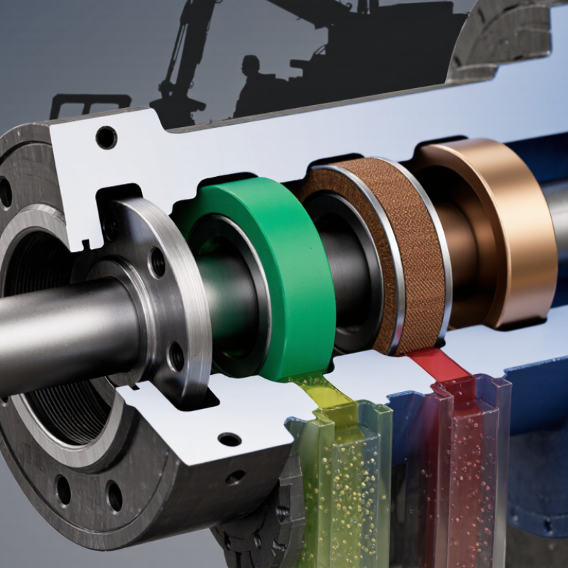
7 Tips for Choosing the Right Hydraulic Guide Ring
Understanding the Function and Role of a Hydraulic Guide Ring
A hydraulic guide ring keeps the piston or rod centered inside the cylinder. It limits metal-to-metal contact during side loading. This small component protects seals, improves alignment, and reduces scoring on the bore surface. Its value becomes clear under pressure. Grand View Research estimates the global hydraulic equipment market reached about USD 49 billion in 2023, with steady growth expected through 2030. More equipment means more demand for reliable guidance components.
Choose the ring by checking seven details: load direction, material, clearance, temperature, fluid compatibility, contamination, and inspection access. Polyamide rings suit many general applications, while filled PTFE can perform better under heat or low-friction requirements. Always compare the supplier’s pressure and speed data with ISO 4413 safety principles. A ring that fits loosely may permit impact. One fitted too tightly may seize when temperatures rise. Small errors matter.
The weak point is often the first assumption. More clearance is not always safer. Field technicians frequently find premature wear after ignoring side loads from poor mounting. Measure the groove, bore, and piston diameter with calibrated tools. Check the ring after a short operating cycle. Look for flattening, scratches, or uneven contact. NFPA industry reporting continues to highlight maintenance and component reliability as important fluid-power concerns. A practical selection should survive real dirt, heat, vibration, and imperfect installation. Perfect laboratory conditions are rarely available.
Selecting a hydraulic guide ring starts with the fluid, not the catalog drawing. Start with the fluid. Mineral oil, water-glycol, and biodegradable fluids affect polymers differently. ASTM D471 reports changes in rubber volume, mass, hardness, and tensile strength after liquid exposure. Request results using your actual fluid, temperature, and exposure period. Compatibility charts help, but they are not complete.
Temperature can change the material decision quickly. PTFE-based compounds suit low friction and chemical resistance. POM and fabric-reinforced phenolic materials often provide stronger load support. Check continuous and peak temperatures separately. ISO 6743-4 classifies hydraulic fluids by family, helping engineers compare fluid chemistry. A ring rated for 100°C may still fail during short thermal spikes. I have seen this overlooked.
Contamination also deserves attention. ISO 4406 records particles at 4, 6, and 14 micrometres per millilitre. Hard particles can score the guide ring, enlarge clearance, and create more debris. Match hardness and embedability to the system’s cleanliness target. Test it first. Then verify pressure, speed, side load, and groove dimensions through cylinder acceptance testing aligned with ISO 10100. Do not rely on pressure alone. Real cylinders experience misalignment, dry starts, and temperature cycling. Sometimes the strongest material wears faster. That trade-off needs a bench test.
| Tip | Operating Condition to Assess | Common Guide Ring Material | Typical Working Temperature* | Typical Material Characteristics | Recommended Application |
|---|---|---|---|---|---|
| 1. Match the material to the temperature | Continuous and peak temperature of the hydraulic fluid and cylinder assembly | Glass-fiber-reinforced polyester resin or fabric-reinforced phenolic resin | Approximately −40°C to +120°C, depending on grade | Good dimensional stability, compressive strength, and resistance to extrusion | General hydraulic cylinders operating at moderate temperatures |
| 2. Consider side load and alignment | Radial load, piston-rod deflection, uneven loading, and potential misalignment | Fabric-reinforced phenolic resin or high-strength thermoplastic composite | Approximately −40°C to +120°C | High load capacity, low friction, and good resistance to deformation under intermittent side loads | Mobile equipment, lifting systems, and cylinders exposed to off-axis forces |
| 3. Check pressure and extrusion risk | System pressure, shock loading, clearance, and groove support | Glass-filled PEEK or reinforced engineering thermoplastic | Approximately −50°C to +150°C; some PEEK grades can tolerate higher temperatures | Very high compressive strength, low creep, and strong resistance to extrusion | High-pressure, high-load, or high-temperature hydraulic applications |
| 4. Evaluate friction and running speed | Piston or rod velocity, start-stop frequency, and allowable frictional heat | PTFE compound filled with bronze, carbon, or glass fiber | Approximately −50°C to +200°C, grade dependent | Low friction, good anti-stick-slip behavior, and suitable performance at low speeds | Servo cylinders, precision actuators, and applications requiring smooth motion |
| 5. Confirm fluid and chemical compatibility | Mineral oil, water-glycol, biodegradable fluid, phosphate ester, or special media | PEEK, PTFE compound, or compatible polyester composite | Varies by fluid and compound; commonly −40°C to +150°C | Chemical resistance varies significantly by polymer, filler, and hydraulic fluid | Fire-resistant, biodegradable-fluid, and chemically demanding hydraulic systems |
| 6. Account for moisture and outdoor exposure | Water absorption, humidity, rain, wash-down, dirt, and corrosion exposure | PTFE compound or low-moisture-absorption PEEK | Approximately −50°C to +150°C, depending on grade | Low water absorption and good resistance to moisture-related dimensional change | Marine equipment, agricultural machinery, outdoor cylinders, and wash-down environments |
| 7. Verify geometry, clearance, and wear life | Rod or bore diameter, groove width, radial clearance, expected cycles, and contamination | Application-specific reinforced thermoplastic or phenolic composite | Select according to the compound and sealing system | Correct dimensions reduce uneven wear, extrusion, heat generation, and seal damage | All hydraulic cylinders; final selection should be validated by calculation and testing |
*Temperature ranges are typical engineering guidance for commonly used material families. Actual limits depend on the specific compound, hydraulic fluid, pressure, speed, clearance, surface finish, and manufacturer data.
Choosing the right hydraulic guide ring starts with dimensions, not price. The ring’s inside diameter must suit the piston or rod, while its outside diameter must fit the groove precisely. Its width also matters. A narrow ring can tilt under side load; an oversized ring may prevent proper seal movement.
Tip 1: Measure the actual groove, not only the drawing. ISO 5597 provides useful guidance for hydraulic cylinder sealing spaces. Check groove depth, width, corner radius, and running clearance. Tip 2: Match the ring with the seal profile. The guide ring must support the piston without squeezing the primary seal. Tip 3: Confirm the cylinder bore and rod diameter under operating temperature. Materials expand, and I have seen small clearance errors become scoring problems.
Tip 4: Consider pressure, speed, temperature, and side load together. A ring designed for low-speed service may fail in a fast reciprocating cylinder. Tip 5: Select a material compatible with the hydraulic fluid. Tip 6: Check split-gap design and installation limits. Tip 7: Request dimensional inspection records before approval. A 2024 Grand View Research analysis valued the global hydraulic-cylinder market at approximately USD 15 billion in 2023, reflecting broad use in construction and industrial equipment. That scale increases the cost of preventable fit errors. ISO 6020/2 and ISO 6022 can also help verify cylinder dimensional expectations, although real operating conditions still require engineering judgment. I would recheck every measurement. Drawings are not always reality.
Matching ring dimensions with cylinder and seal specifications starts with the cylinder bore, piston diameter, groove width, and the application’s expected side load. The chart shows practical screening ranges for common hydraulic cylinder bore sizes.
Use the bore size as the first reference, then verify the guide ring’s inside diameter, outside diameter, width, and radial clearance against the piston, housing groove, seal envelope, pressure, temperature, and side-load requirements. The values shown are typical engineering screening ranges; final dimensions must be checked against the cylinder drawing and seal manufacturer’s specification.
Start with the cylinder’s real pressure, not its catalog maximum. ISO 6020/2 specifies 160 bar nominal pressure for compact hydraulic cylinders, while ISO 6022 covers designs rated around 250 bar. A guide ring must tolerate side loading during these cycles. Check bore size, rod diameter, clearance, and stroke speed together. Pressure alone can mislead.
Pressure matters. Temperature changes material behavior. Confirm the ring’s continuous and peak temperature limits against the actual fluid and duty cycle. ISO 4406 cleanliness codes show how particle contamination is classified by size. This matters because abrasive particles can score the ring, enlarge clearance, and increase leakage. Select a material compatible with mineral oil, water-based fluid, or the specified synthetic fluid. Do not assume compatibility.
Measure side load from the rod, piston, or external structure. Compare it with the ring’s permissible bearing pressure and PV limit, using the supplier’s test data. Include starts, stops, shock loads, and misalignment. A wider ring may reduce surface pressure, but it can also restrict lubrication. In field inspections, uneven wear often reveals alignment problems rather than weak material. That is easy to miss. Review ISO 6020/2 or ISO 6022 requirements, test the assembly at operating temperature, and leave a documented safety margin for pressure, heat, and load.
Choosing a hydraulic guide ring involves more than matching the bore diameter. Confirm groove width, depth, corner radius, piston clearance, and allowable side load. A loose ring may twist during cycling. Too tight? It can restrict movement or damage the groove. Measure the actual cylinder when possible, because worn equipment rarely matches old drawings. Also consider fluid compatibility, operating temperature, pressure, and expected load.
Installation conditions deserve equal attention. Clean the cylinder thoroughly, remove burrs, and inspect the groove under bright light. Even a small metal chip can score the rod or piston during the first stroke. Use a compatible lubricant, then press the ring evenly into position. Do not force it with a sharp screwdriver. That shortcut often creates cuts that appear only after pressure rises. Check the joint, orientation, and free movement before assembly.
Long-term maintenance should reflect heat, pressure, fluid type, load, and duty cycle. During scheduled service, inspect for flattening, cracks, extrusion marks, uneven wear, and embedded particles. Uneven wear needs investigation. It may indicate misalignment, excessive side loading, poor lubrication, or incorrect clearance. Record operating hours and leak patterns instead of relying on memory. A fixed service interval helps, but conditions can change. Our judgment can fail there. A ring may look acceptable while its supporting function has already declined.
Match the inside diameter to the piston or rod. Match the outside diameter to the groove. Check ring width carefully. A narrow ring may tilt. An oversized ring may restrict seal movement.
Measure groove depth, width, corner radius, and running clearance. Measure the actual cylinder when possible. Old drawings may not reflect wear. Reality can disagree.
The ring should support the piston without squeezing the primary seal. Check piston clearance and seal movement. A tight fit can increase friction and damage nearby parts.
Consider pressure, speed, temperature, side load, and stroke together. Pressure alone can mislead. A slow-service ring may fail in fast reciprocating equipment.
Match the ring material with the actual fluid. Check mineral oil, water-based fluid, or synthetic fluid requirements. Do not assume compatibility. Confirm continuous and peak temperatures too.
Measure loads from the rod, piston, and external structure. Compare them with permissible bearing pressure and PV limits. Include starts, stops, shock loads, and misalignment. Uneven wear may reveal alignment problems.
Clean the cylinder thoroughly. Remove burrs and inspect the groove under bright light. Use compatible lubricant. Press the ring evenly. Avoid sharp screwdrivers. A tiny metal chip can score the piston during the first stroke.
Inspect for flattening, cracks, extrusion marks, uneven wear, and embedded particles. Record operating hours and leak patterns. Investigate uneven wear. It may indicate poor lubrication, excessive load, or incorrect clearance.
Yes. Request inspection records for diameter, width, and groove fit. Test the assembly at operating temperature. Keep a documented safety margin. I would recheck every measurement.
Choosing the right Hydraulic Guide Ring is essential for maintaining cylinder stability, reducing friction, and preventing unwanted contact between moving components. Start by understanding its role in guiding the piston or rod while supporting smooth, accurate movement. Then select a material suited to the operating environment, considering factors such as chemical exposure, moisture, friction, wear, and compatibility with nearby seals. Correct dimensions are equally important, so the ring must match the cylinder groove, piston or rod size, seal design, and required clearance.
Before making a final selection, evaluate the expected pressure, temperature range, side loads, and operating speed to ensure the ring can withstand working conditions without deforming or wearing prematurely. Installation requirements should also be reviewed, including groove accuracy, surface condition, alignment, and fitting method. Finally, consider long-term maintenance by checking inspection intervals, lubrication needs, replacement procedures, and signs of wear. A well-chosen ring can improve reliability, extend component life, and reduce unexpected maintenance.

Kelong New Materials