Why Choose Chemical Resistant Rubber Hose?
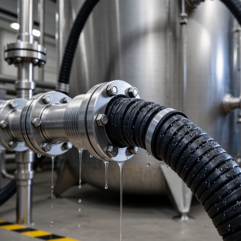
In industrial environments, hose failure can begin quietly. A slight swelling, softened inner wall, or sharp chemical odor may appear first. These warning signs often indicate material incompatibility. Chemical Resistant Rubber Hose is designed to handle demanding fluids while maintaining flexibility, pressure performance, and structural stability.
Its value becomes clear in chemical processing, laboratories, water treatment, agriculture, and manufacturing. A properly selected hose can transport acids, alkalis, solvents, oils, and other aggressive media more safely. Reinforced layers help control expansion under pressure. The rubber cover can also resist abrasion, sunlight, heat, and rough handling. However, resistance is never universal. Concentration, temperature, exposure time, and pressure can change performance significantly.
Real-world selection requires more than reading a product label. Engineers should review chemical compatibility charts, operating temperatures, working pressure, bend radius, and connection methods. A hose used near a heated tank may need different protection from one used for brief transfer operations. Inspect the hose regularly. Check for cracks, blisters, stiffness, discoloration, and damaged fittings. Small defects can become expensive failures.
The best choice balances safety, service life, flexibility, and total operating cost. Still, no hose eliminates every risk. Compatibility data may not reflect every site condition, and assumptions should be tested carefully. Consulting qualified manufacturers or engineers adds practical confidence. With disciplined selection and maintenance, Chemical Resistant Rubber Hose can support cleaner operations, fewer interruptions, and more reliable fluid handling.
Why Choose Chemical Resistant Rubber Hose?
Chemical resistance depends on the compound, not the hose appearance. EPDM handles many diluted acids, alkalis, salts, and outdoor conditions. It is a practical choice for water-based chemicals. However, EPDM performs poorly with petroleum oils and many fuels. NBR offers better resistance to oils, diesel, and hydraulic fluids. Its weakness appears with ozone, sunlight, and some aggressive chemicals. FKM tolerates many fuels, solvents, oils, and elevated temperatures. Still, it is not automatically suitable for hot water, steam, or concentrated chemicals. The exact formulation matters.
PTFE liners provide the broadest chemical resistance in many hose designs. They resist strong acids, solvents, oxidizers, and high-purity fluids. Their smooth surface also reduces residue buildup. Yet PTFE is not a universal answer. Mechanical damage, permeation, bending radius, and temperature cycling still require attention. The liner may survive the chemical while the outer cover fails outside.
Field selection should begin with the chemical name, concentration, temperature, pressure, and exposure time. We have seen a hose pass a room-temperature test but fail after continuous heating. That detail is easy to miss. Compatibility charts are useful, but they are not final approval. Check the complete assembly, including fittings and seals. A slightly cautious choice is often cheaper than an unexpected leak. Even so, over-specifying every hose can raise cost without improving safety. Test the real fluid when uncertainty remains.
Why Choose Chemical Resistant Rubber Hose?
A chemical resistant rubber hose should be selected through evidence, not appearance. In testing, ISO 1817 immerses rubber specimens in defined liquids, temperatures, and exposure periods. The laboratory records volume before and after immersion. Volume change is commonly calculated as [(V2 − V1) / V1] × 100. Positive results indicate swelling, while negative results show shrinkage. Both can weaken a hose.
ASTM D471 follows a similar purpose but includes its own specimen requirements and conditioning details. Technicians may also measure mass, hardness, tensile strength, and elongation after exposure. A small volume increase can still affect fittings, flow, and reinforcement contact. For example, a hose exposed to heated oil may soften and expand around its inner tube. It may look acceptable from outside.
Testing must reflect actual service conditions. Use the correct chemical concentration, temperature, pressure, and exposure time. A room-temperature result cannot fully predict performance at 90°C. We have seen clean test data mislead selection when the laboratory fluid differed from the operating fluid. That weakness deserves attention. ISO 1817 and ASTM D471 results should be compared carefully, because methods and reporting details may vary. Record specimen dimensions, fluid changes, visual damage, and post-test measurements. Small cracks matter. Temperature control matters. Reliable hose selection comes from repeatable testing and honest interpretation, not a single impressive number.
Test Methods and Data: ISO 1817 Volume Change and ASTM D471
This chart compares nominal immersion periods commonly used when evaluating rubber volume change after chemical exposure. ISO 1817 includes multiple exposure intervals from 24 to 1008 hours, while ASTM D471 commonly uses a 70-hour standard immersion period. Longer exposure periods can help reveal delayed swelling, shrinkage, or degradation that may not be visible during short-term testing.
Reference basis: ISO 1817 and ASTM D471 test-period conventions. Actual volume-change results depend on the rubber compound, chemical, temperature, and exposure conditions.
Why Choose Chemical Resistant Rubber Hose?
Selecting a chemical resistant rubber hose requires more than matching a fluid name. Pressure and temperature often change together. A hose rated for 10 bar at room temperature may require a lower working pressure at 80°C. EN 12115 ratings provide a useful reference for chemical hose assemblies, but they do not replace application review. Check the working pressure, test pressure, temperature range, and chemical compatibility for the complete assembly. The lining, reinforcement, couplings, and seals must suit the same service conditions.
Vacuum service needs separate attention. Positive pressure strength does not automatically guarantee safe suction performance. A hose may collapse when exposed to vacuum, especially near its maximum temperature or bending radius. Confirm the vacuum rating and support the hose correctly during operation. Leave a practical safety margin below the published limits. Pressure surges, pumping cycles, and outdoor heating can create conditions that a simple specification sheet misses. I have seen otherwise suitable hoses fail because the real temperature was higher than the recorded process temperature.
Tips: Record pressure and temperature at the hose, not only at the equipment. Consider start-up peaks, cleaning cycles, and accidental blockage. Keep bends smooth and inspect for swelling, cracks, or softened covers. Replace uncertain assemblies rather than guessing. No chart replaces field judgment. Recheck the selection after any process change.
| Selection Dimension | Reference Value or Rating | Typical Operating Condition | Pressure–Temperature Consideration | Safety Requirement | Practical Selection Guidance |
|---|---|---|---|---|---|
| EN 12115 Pressure and Temperature Selection | |||||
| EN 12115 working-pressure class | 10, 16, 25 or 40 bar | Positive-pressure transfer of chemicals | The selected hose rating must be equal to or higher than the maximum system pressure at the actual service temperature. | Do not use the nominal pressure class as a guaranteed rating at every temperature. | Check the hose assembly certificate and pressure–temperature chart for the exact construction, lining and reinforcement. |
| Minimum burst-pressure relationship | Typically at least 4 times the specified working pressure for EN 12115 hose assemblies | Proof of pressure containment under a defined test condition | Burst pressure is a test requirement, not an allowable operating pressure. | Maintain the full specified working-pressure limit; never operate at burst pressure. | For a 16 bar working-pressure hose, the minimum specified burst level is commonly 64 bar when the applicable EN 12115 construction requires a 4:1 ratio. |
| Ambient and media temperature | Must remain within the hose manufacturer's stated range | Continuous or intermittent chemical service | Higher temperature can reduce elastomer strength, accelerate ageing and lower the allowable working pressure. | Use the lowest applicable pressure rating after temperature derating. | Evaluate the temperature of the chemical, hose wall and surrounding environment, including hot flushing and steam exposure. |
| Common elastomer temperature guidance | EPDM: commonly about −40 to +120 °C; FKM: commonly about −20 to +200 °C; NBR: commonly about −30 to +100 °C | General material-selection comparison only | Actual limits depend on compound, concentration, pressure, flexibility requirements and exposure duration. | These are not universal EN 12115 ratings. | Use the product-specific temperature curve and chemical-compatibility data instead of selecting by elastomer name alone. |
| Vacuum and Mechanical Service | |||||
| Vacuum service | Specified separately from positive pressure | Vacuum loading, suction, tank unloading and pump inlet service | Vacuum resistance can decrease at elevated temperature, with larger bend radius, or when the hose is exposed to external compression. | Do not assume that a pressure-rated hose is suitable for full vacuum. | Confirm the stated vacuum rating, temperature limit and minimum bend radius for the complete hose assembly. A full vacuum is approximately −1 bar gauge at sea level. |
| Anti-static or electrically continuous construction | Required where static charge could create an ignition or shock hazard | Flammable solvents, fuel-like liquids, powders or high-flow chemical transfer | Electrical continuity may be affected by hose length, fittings, couplings, contamination and assembly method. | Test continuity after assembly and during the inspection program; bond and ground the transfer system as required by the site risk assessment. | Specify the required electrical category under EN 12115 and verify continuity through the hose, fittings and connection points. |
| Minimum bend radius | Defined by the hose construction and nominal bore | Fixed routing, loading arms and frequent movement | Excessive bending can kink the hose, restrict flow, damage reinforcement and reduce pressure capability. | Never bend below the published minimum bend radius, especially while pressurized or under vacuum. | Allow additional routing length for movement and prevent twisting at the coupling. |
| Nominal bore and flow velocity | Selected from required flow rate, allowable pressure loss and chemical properties | Liquid transfer and pumping operations | A smaller bore increases velocity and friction loss; abrupt restrictions can increase turbulence and static generation. | Confirm pump inlet conditions and avoid flow rates that cause cavitation or unacceptable pressure drop. | Size the bore from the actual flow rate rather than selecting by coupling size only. |
| Chemical Resistance and Safety Margins | |||||
| Chemical compatibility | Must be confirmed for the fluid, concentration, temperature and exposure time | Acids, alkalis, solvents, oils, oxidizers and mixed chemicals | Compatibility can change substantially with concentration and temperature; permeation may occur even when visible degradation is absent. | Do not rely only on a general chemical-resistance chart for critical service. | Check lining, cover, tube reinforcement, gaskets and couplings as one complete chemical-contact system. |
| Recommended pressure margin | Working pressure should not exceed the hose rating at service temperature | Normal operation with pressure fluctuations | Allow for pump pulsation, water hammer, valve closure and start-up surges. | A practical engineering approach is to select the next higher pressure class when transient pressure is uncertain. | Document the maximum steady pressure and maximum transient pressure before selecting the hose. |
| Pressure-test condition | Follow the applicable standard, site procedure and assembly instructions | Commissioning, periodic inspection or post-repair testing | Hydrostatic testing is generally preferred to pneumatic testing because stored energy is lower. | Keep personnel clear of pressurized assemblies and never exceed the approved test pressure or test duration. | Record test date, pressure, duration, assembly identification and inspection result. |
| Inspection and replacement indicators | Leaks, blisters, cuts, exposed reinforcement, kinks, cover cracking, corrosion or damaged couplings | Routine service inspection | Chemical attack may occur internally before external damage becomes visible. | Remove the hose from service immediately if reinforcement is exposed, leakage occurs or the coupling is displaced. | Use a documented inspection interval based on chemical severity, operating cycles, temperature and consequence of failure. |
| Final selection rule | Pressure, temperature, vacuum, chemical compatibility and mechanical limits must all be satisfied | Complete hose-and-coupling assembly | The lowest applicable limit governs the safe operating envelope. | Select the assembly by its most restrictive verified rating, not by pressure rating alone. | Obtain current technical documentation for the exact hose construction and fitted coupling before placing it into service. |
Chemical resistant rubber hoses protect more than process fluids. They also manage static electricity during transfer. Solvents, acids, and powders can generate charge as they move. A conductive hose provides a controlled path for dissipation when correctly bonded and grounded.
EN 12115:2021 uses 10⁶ Ω as the maximum resistance criterion for conductive hose assemblies. This value is practical, not decorative. A technician should test continuity before service, after installation, and during scheduled inspections. NFPA 77, 2024 edition, also emphasizes bonding and grounding as essential static-control measures. One reading is never enough.
A low resistance result does not prove complete electrical safety. Moisture, chemical swelling, damaged wires, or loose couplings can change performance. Our judgment can fail here. The hose may look clean while its conductive layer is already compromised.
Test records should include temperature, hose length, connection points, and measured resistance. EN 12115 also links hose selection to chemical compatibility, pressure, temperature, and construction. Chemical resistance therefore supports electrical reliability, but it cannot replace inspection. In practical work, a hose below 10⁶ Ω is only one part of a safe transfer system.
Chemical resistant rubber hose selection begins with the fluid, temperature, pressure, and exposure time. A suitable hose should resist swelling, softening, cracking, and chemical permeation under actual operating conditions. Laboratory compatibility charts help, but field conditions can differ. Heat, repeated flexing, and trapped residue may accelerate damage.
ISO 8331 provides practical guidance for selecting, storing, using, and maintaining rubber hose assemblies. It does not create one universal replacement date. Inspect hoses before operation and at scheduled intervals. Look for blisters, cuts, surface cracks, discoloration, stiffness, flattening, and exposed reinforcement. Check the couplings too. Movement at the connection can reveal internal stress. A hose may look clean outside while its inner tube has weakened.
Bend radius deserves close attention. Bending below the specified minimum radius can kink the hose, restrict flow, and damage reinforcement. Measure the bend during installation, not only when the line is empty. Replace a hose after visible chemical attack, leakage, reinforcement exposure, or unexplained loss of flexibility. Replace it sooner when service history is unknown. This is not always convenient. It is often safer than trusting appearance alone. Keep inspection records with installation dates, fluids handled, pressure conditions, and observed defects. Some judgments remain imperfect, especially when internal damage cannot be seen.
Test specimens are immersed in defined liquids, temperatures, and exposure periods. Their volume is measured before and after immersion.
The calculation is (V2 − V1) / V1 × 100. Positive values show swelling. Negative values show shrinkage.
Yes. Swelling may affect fittings, flow, and reinforcement contact. Heated oil can soften an inner tube.
Chemical concentration, temperature, pressure, and exposure time should reflect real operation. Room-temperature data may mislead at 90°C.
Its resistance should remain below 10⁶ ohms under applicable testing conditions. Bonding and grounding provide the intended discharge path.
No. Moisture, swelling, damaged conductive layers, and loose couplings can change performance. Test continuity before service and during inspections.
Check for blisters, cuts, cracks, discoloration, stiffness, flattening, and exposed reinforcement. Inspect couplings and connection movement too.
Replace it after leakage, chemical attack, exposed reinforcement, or unexplained loss of flexibility. Unknown service history deserves caution.
Bending below the specified minimum radius can kink the hose, restrict flow, and damage reinforcement. Measure it during installation.
Not reliably. The outside may look clean while the inner tube has weakened. Our judgment can still be wrong.
A Chemical Resistant Rubber Hose is designed to safely transfer aggressive fluids while maintaining flexibility, pressure performance, and service reliability. Selecting the right liner is essential: EPDM is suitable for many acids, alkalis, and water-based chemicals; NBR performs well with oils and fuels; FKM offers strong resistance to heat and hydrocarbons; and PTFE provides broad chemical compatibility and a low-friction internal surface. Material selection should be verified through ISO 1817 volume-change testing and ASTM D471 evaluations to assess swelling, softening, and degradation.
Correct pressure–temperature selection is equally important. EN 12115 ratings, vacuum resistance, and appropriate safety margins should be considered together, especially when operating conditions fluctuate. For applications involving static electricity, conductive hose designs with electrical resistance below 10⁶ Ω under EN 12115 can help control charge accumulation. Regular inspection should follow ISO 8331 guidance, with attention to bend radius, surface damage, leakage, aging, and reinforcement exposure. Replacing the hose before critical deterioration helps protect personnel, equipment, and the process.

Kelong New Materials